CompTIA A+ Core 1: Cable Types & Connectors
Table of Contents
1. Video: Course Overview (it_csap121_06_enus_01)
2. Video: Ethernet Cable Types (it_csap121_06_enus_02)
3. Video: STP vs. UTP (it_csap121_06_enus_03)
4. Video: Optical Fiber Cabling (it_csap121_06_enus_04)
5. Video: Speed and Transmission Limitations (it_csap121_06_enus_05)
6. Video: T568A/T568B Wiring Codes (it_csap121_06_enus_06)
7. Video: Video Cables (it_csap121_06_enus_07)
8. Video: USB Cables Types (it_csap121_06_enus_08)
9. Video: Peripheral Serial Cables (it_csap121_06_enus_09)
10. Video: Hard Drive Cables (it_csap121_06_enus_10)
11. Video: Common Adapter Types (it_csap121_06_enus_11)
12. Video: RJ-11 and RJ-45 Connectors (it_csap121_06_enus_12)
13. Video: USB Connector Types (it_csap121_06_enus_13)
14. Video: Fiber Optic Connectors (it_csap121_06_enus_14)
15. Video: Punch Down Blocks (it_csap121_06_enus_15)
16. Video: DB-9, Lightning Ports, and F Connectors (it_csap121_06_enus_16)
1. Video: Course Overview (it_csap121_06_enus_01)

- discover the key concepts covered in this course
Hi, I'm Aaron Sampson and I've been a professional in the IT industry since 1995, with the primary focus on technical training,
[Video description begins] Your host for this session is Aaron Sampson. He is an IT trainer and a consultant. [Video description ends]
I can be found most of the time producing and delivering learning content centered around network infrastructure and services. I've also been involved with extensive practical implementations in a variety of operational capacities, including architecture and design, deployment and implementation, administration and management, and various other technology-based roles. Today's IT technicians need to familiarize themselves with the vast array of cable options and connector types.
In this course, we'll explore the most common cable types and adapters encountered when working with computers and mobile devices, including network, video, multipurpose, peripheral, and hard drive cables. I'll explore different Ethernet cable types such as Cat5, Cat5e, Cat6, and Plenum cable. Next, I'll examine the differences between shielded twisted pair and unshielded twisted pair cabling, and explore the basics of fiber optic and coaxial cabling. I'll examine the speed and transmission limitations of different network cables and discuss different video cables such as VGA, HDMI, mini HDMI, DisplayPort, and DVI.
From there, you'll learn about using lightning and Thunderbolt cables, examine USB cables and the differences between the USB versions. Next, I'll explore serial peripheral cables and hard drive cables such as Serial ATA, IDE, and SCSI and will differentiate between adapters such as DVI to HDMI, USB to Ethernet, and DVI to VGA. Lastly, we'll explore several different connectors and converters likely to be encountered when working in computing environments. This course will help to prepare learners for the CompTIA A+ Core 1 or 220-1101 certification exam.
2. Video: Ethernet Cable Types (it_csap121_06_enus_02)
- differentiate between ethernet cable types such as Cat5, Cat5e, Cat6, Cat6a, coaxial, and plenum
For our first video of this course, we'll examine the common types of networking cables in use these days, most of which are categorized with respect to their capabilities. Hence, they are often referred to by their category. For example, category 5 cable or Cat 5 is often the way this cable is referenced. The structure of the cable internally is made up of eight individual copper wires that themselves are coated with a plastic sheeting, but there are four pairs of wires that are each twisted around each other, which helps to reduce interference. Hence, this cable is also referred to as twisted pair. In terms of specifications, category 5 cable can provide speeds of up to 100 Mbps and it's also suitable for voice and video. But due to its comparatively low speed these days category 5 has largely been superseded by category 5e and some of its later successors.
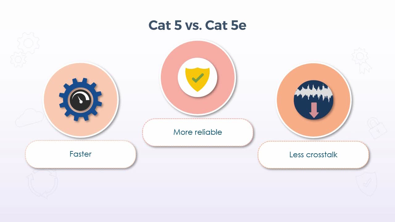
So, then the e in category 5e stands for enhanced and most notably it supports significantly greater speeds than category 5, up to 1 Gbps. And provides more reliable transmissions by making improvements to the materials, resulting in 5e being better at ignoring crosstalk or interference from the wires within the cable itself. 5e is also backward compatible with 5, but it will only operate at the specifications of 5, if the devices to which it is connected only support that level of performance. Cat 6 cabling is the next iteration and also consists of four internal pairs of twisted wires, but it increases the transmission frequency from 100 Mhz in Cat 5 and 5e to 250 Mhz, resulting in yet another significant increase in speed, supporting up to 10 Gbps, while still remaining backward compatible with both Cat 5 and 5e.
But again, it will only operate at the lower performance level. If the device is being used, don't support category 6 specifications. Like Cat 5e, Cat 6a is an augmented version of Cat 6 and implements tighter winding of the internal wires, resulting in more copper per inch and an extra thick layer of plastic around the wires themselves is used, which further reduces crosstalk and signal loss. Cat 6a also doubled the transmission frequency up to 500 Mhz, which at present still only offers the same 10 Gbps speed as Cat 6. But 6a can maintain that speed at greater distances than standard Cat 6. Now I should mention that at the time of this recording, Cat 7 and even Cat 8 are available, and as you might imagine, each improves upon its predecessors with greater speed and less interference, but they aren't particularly common just yet, and prices remain higher than their earlier counterparts.
But at 10 Gbps, Cat 6 or 6a is more than adequate for most of today's environments. Now, plenum cabling really has nothing to do with the performance characteristics of the cable. And each of the categories mentioned to this point would be available in plenum versions, so to speak. But the plenum itself is actually the space in a building where utilities such as heating or air conditioning ducts, water pipes, or power cables are run. Typically, it's the space between the ceiling of one level and the floor of the next. While the plenum space provides the ability to hide all of those utilities, it's also very open and represents a fire hazard, because it can allow smoke and toxins to easily pass from space to space.
Hence, plenum cables are made from fire-retardant materials, which produce less smoke and lower levels of toxic chemicals when burned, including low smoke polyvinyl chloride or PVC and Teflon, which are also commonly self-extinguishing. Now, plenum cable often tends to be less flexible, so it can be a little more difficult to work with if you have to go around a lot of obstacles. But that usually doesn't present a problem in the plenum space, because most cables can be run in fairly straight lines. So, if you find yourself working on cable runs that have to go through plenum space, fire codes in most regions and countries will require the use of plenum rated cable. Coaxial cable in today's networking environments would certainly be among the oldest types of network cabling.
In fact, I'd honestly be very surprised if it was in use at all these days, at least for networking. It was prevalent in the early days of networking, but that's literally going back over 30 to 35 years. Coaxial cable used a single copper core wire as opposed to the eight wires we see in other categories, plus a braided wire mesh that was used to insulate the core and provide shielding from noise and interference. Now, while it is virtually extinct in LAN environments, you may still see coaxial cable used by some Internet service providers, although this is also becoming outdated rather quickly in favor of fiber optics. But cable Internet, as it was known, was one of the first implementations of high-speed Internet at home, and again, may still be in use in some areas. A typical coaxial cable construction included the outermost jacket which was typically some kind of plastic.
Then the braided wire mesh and a solid foil shield provided the insulation. The dielectric layer was also made from plastic and simply functioned as a non-conductive material which ensured that the conductive core kept as much of its own signal as possible within the core. Now, coaxial cable has a few different implementations and specifications as well. For example, if you do encounter cable Internet, it will typically be using the RG-6 specification. The RG stands for Radio Guide and RG-6 cable is in fact the same coaxial cable that was previously used with cable television. But it required a specific cable modem which used the coaxial cable from signal coming in from your Internet service provider but had standard Ethernet outputs, so that you could connect your computer or a switch to the modem. RG-6 has a 75-ohm resistance and uses an 18-gauge center conductor.
It was also available with quad-shielded versions which provided better insulation against interference, making it a better option for today's HDTV signals if it's being used for television. RG-59 is typically used in older cable, satellite or closed-circuit TV installations, and uses a thinner 22-gauge core that also has a 75-ohm resistance, but only a single outer shield, making it a little more susceptible to interference. Hence, the reason it's not really used for many newer applications. Now, coaxial cable did have some benefits, but I do want to point out that most of these would only be applicable to when it's being used for high-speed Internet as opposed to being in a LAN environment. So, with that said, coaxial cable does support multiple channels on the same cable, which is also referred to as broadband transmissions.
Standard Ethernet uses baseband transmissions, which means that 100% of the available bandwidth is allocated to the digital signals on the cable at any given time. Now, this is perfectly fine for data on an Ethernet LAN, because there are only zeros and ones being transmitted back and forth. So, if you imagine the cable as a cross section of a pipe with a wave like pattern representing the data transmissions, then imagine the 0 value as being at the very bottom of the pipe and the 1 value as being at the very top. In other words, there's nothing in between. But broadband transmissions can be visualized as many different variations in the wave pattern with any one of those patterns falling anywhere in between the top and bottom.
But all of them can travel down the same pipe at the same time, which if we refer back to television for a moment, is what we see as all the different channels that are provided over a single cable. In fact, for anyone who did have cable Internet, if you disconnected the cable modem and hooked up a television to the same cable, there was standard cable TV on that cable. So, the Internet data signals simply used a specific and dedicated channel of the cable to distinguish it from the standard television channels. But getting back to the cable itself for these types of transmissions, it did have lower error rates as compared to Ethernet cabling, had a high capacity in terms of speed and a rigid design that made it more durable.
On the downside, the large solidcore did produce some data leakage and was more susceptible to interference than Ethernet cabling. And the rigid design that could be a plus in terms of durability also made it a little more difficult to work with in situations where you actually needed more flexibility. Again, these days, coaxial cable is rapidly disappearing, but not out of the picture just yet. And you may also still find it being used for certain types of specific equipment, so it's still worth knowing the specifications. But in any standard networking environment, categories 5 and 6 and their variations will almost certainly be what you'll encounter.
3. Video: STP vs. UTP (it_csap121_06_enus_03)
- differentiate between shielded twisted pair (STP) and unshielded twisted pair (UTP) wiring
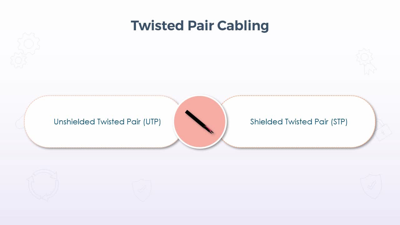
In this presentation, we'll examine some of the basic characteristics of twisted pair cabling, most notably the distinction between unshielded and shielded. But, for starters, let's look at the characteristic that's common to both types, which is the twisted pair. Virtually all forms of Ethernet cable in the last 20 to 30 years have used this type of construction, which simply refers to the fact that inside the exterior jacket of the cable, there are eight individual wires, but those eight wires are divided up into four pairs. Then each pair is twisted around each other, which itself is done to help reduce the level of interference and crosstalk that could occur, otherwise, if the wires were just run straight down the cable.
In other words, the twisting provides a certain level of inherent shielding, but this largely refers to shielding against interference and crosstalk from the internal wires themselves. For instance, the signals on any given wire might be picked up by another wire. But then in other situations the cable may be run in an area where there are high levels of interference from external sources, such as strong radio emissions or power sources, so additional shielding is required to protect those cable runs. Hence, we have both unshielded twisted pair or UTP and shielded twisted pair or STP. So then, in terms of comparison, as mentioned, both implement the twisted pair construction, but shielded or STP adds foil and or a mesh to the inside of the cable to reduce the level of noise and interference, which, of course, is a plus.
But it also requires the use of an electrical ground, which increases the complexity of working with shielded cable. But I'll discuss that in greater detail in just a moment. So then, in terms of construction, if we look at an example of unshielded cabling, we have the eight individual wires which are typically color coded, with each pair having a solid-colored wire, then that same solid color but with white stripes. So, for example, one twisted pair would be a solid blue wire, then a blue and white striped wire. The solid colors are usually blue, green, orange and brown. Again, each individual copper wire has its own plastic insulation, then all four twisted pairs are placed inside the exterior protective jacket. Now in shielded twisted pair we have the exact same four twisted pairs, but each pair is protected by a foil shield,
then all four pairs are further protected by a braided shield. Now what you'll also find is what's known as a drain wire, which comes back to the grounding I mentioned a moment ago. Because of the ability for the shielding to conduct electricity, the drain wire remains in contact with the shielding and provides the ability to ground the cable, which must be done on at least one end. Now to clarify, the connector that would be placed into a switch or other networking device uses the same RJ-45 connector as unshielded twisted pair, so there wouldn't be any grounding on that end. But shielded cable almost always tends to be used for the cable runs that terminate back into the central wiring room. In other words, you wouldn't use a shielded cable between your computer and the data port on the wall.
So, in the wiring room, you typically just connect the bare wires to a patch panel, so you don't need an RJ-45 connector. So, the patch panel would have a place to insert the drain wire, then the entire panel itself could be grounded like any other electrical outlet. So, in short, the grounding is done at the end where you terminate to the patch panel. Now that all said, it wouldn't be impossible to ground the other end, because if we are talking about a cable that is being run through the walls between a data port and the patch panel, then you could ground the wire on the end that is in the wall port, provided there's something metal to which the wire could be attached. But again, it's just far more common to simply use the ground that is on the patch panel, and as long as it is grounded on at least one end that is sufficient.
As for some other differences with respect to installation and data rates, UTP tends to be easier to install and work with, because it's more flexible, smaller, which refers to the diameter and lighter. But for the same category cable, such as category 6e, UTP will typically provide slower data rates overall, whereas STP tends to be more difficult to work with because it's more rigid, larger, and heavier than UTP. But again, for the same category, it can provide better data rates. Now to quickly qualify that statement, it's not really that one is capable of higher speeds than the other, rather, it's the fact that since STP is better protected from interference, there will usually be fewer lost or retransmitted packets, resulting in better use of the bandwidth overall. Another use of STP is known as direct burial STP, which as its name indicates is used for underground cable runs, including those that run outdoors or directly underground through a conduit of some type, or even just entirely buried on its own.
With this type of installation, not only is the cable shielded against noise and interference, like standard STP, but it also uses a polyethylene jacket to protect it against the standard elements, such as water and extreme temperatures. In terms of implementation then, UTP is suitable for most home and office environments, or really any environment where the level of noise and interference just isn't a concern. And again, it's almost always the cable that would be used between a computer and the wall port, and even in the wiring room it would also be the cable that is used to connect the patch panel port to something like a switch. If STP is being used, it would almost always be the cable that's running through the walls or ceilings.
UTP is also commonly used for telephone connections these days, since most office environments have implemented voice over IP phones. STP then is ideally used when there is a concern for high levels of electromagnetic interference or EMI, such as in airports, where there could be a lot of radio transmissions, industrial environments, where there might be a lot of power generators, or medical centers, where there might be X rays, or magnetic resonance imagers or MRI machines. In short, UTP is much more commonly used in most environments, but in situations, such as what we've just listed here, STP would certainly be warranted. So, if you find yourself working on a new installation, you simply need to assess if EMI is going to be a potential issue, and if so, put in the extra time and money to implement shielded cabling, because it will cost far more if you put in unshielded, then find that it needs to be replaced further down the road.
4. Video: Optical Fiber Cabling (it_csap121_06_enus_04)
- identify the benefits of fiber cabling
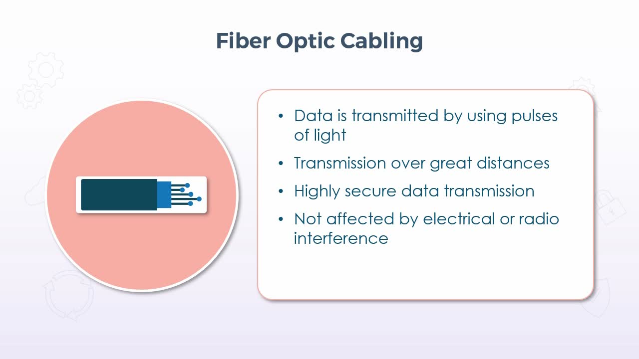
In this presentation, we'll take a look at the basics of fiber optic cabling, which literally transmits data by using pulses of light as opposed to an electromagnetic current over a copper wire. Now this method immediately provides several benefits, including the ability to transmit data over very large distances most notably, because it doesn't suffer from resistance, like a signal on a copper wire does. And because it's just pulses of light, it provides better security than copper wire, because if an intruder has physical access to the cable itself, it is possible to tap into copper wire to intercept data. But if you try to do that with fiber optic cabling, it would just break the core material and you wouldn't be able to pick up on anything. In addition, for all practical purposes, it doesn't suffer from electromagnetic interference from sources, such as power generators or strong radio emissions.
If we look at the cable design, it's comprised of a core where the light itself travels, encased in four layers, which include the cladding, coating, strength member, and outer jacket. The core itself was quite thin, but it doesn't need to be particularly wide to carry pulses of light. Then the core and the cladding actually work together to control the manner by which the light travels through the core, but I'll come back to that in just a moment. The coating is essentially just to act as a barrier so that no light can escape. The strength member does exactly, as its name indicates, it makes the cable stronger, so that it doesn't have to be handled in such a delicate manner. And, of course, the outer jacket just wraps up everything else.
So, coming back to the interaction between the core and the cladding, as mentioned, they work together to control the light pulses using what's known as single-mode versus multi-mode transmissions. And multi-mode itself has two varieties known as step index and graded index. So, in all three modes a light source transmits pulses through a fiber optic cable. So, with step index and graded index in multi-mode, the light source is typically an LED which can produce varying wavelengths, hence the multi aspect of the name. But in both cases the light rays reflect and refract off the internal cladding as they travel through the core. So, with step index what you get is a fairly sharp refraction, which is due to the very thin cladding, which produces very sharp angles. But with graded index the cladding is thicker and the light rays refract in a smoother, more regular manner.
In other words, graded is gradual and step is very sharp. So, it might seem like the graded index is a better choice, and in most cases it probably is, but, of course, it's more expensive. But with single-mode the light source is typically a laser, which can produce a much more tightly focused beam. So, single-mode still uses the step index method, but with a very thick cladding. So, any reflection or refraction may still be sharper, but in terms of implementation, single mode tends to be used over very large distances where the cable can be run in a much straighter manner, so there is simply less reflection and refraction to deal with. Given that, of course, you can also infer that multi-mode cabling tends to be used over shorter distances and when the cable is generally unable to be run in a fairly straight-line manner.
Now, just with respect to the distances, both types are generally able to span distances measured in kilometers, but in more practical terms you would likely find multi-mode cabling in LAN environments, and single-mode in WAN or MAN implementations. As for the connectors on fiber optic cabling, they are specifically designed for the optical transmissions and generally determine the behavior of the light pulses from the source as it moves on to the cable. Three very common types include the SC or subscriber connector, which is also commonly referred to as the square connector due to its shape, the LC or lucent connector and the ST or straight tip. Each has its specific use and or pros and cons, but these days the straight tip is probably more common than either the SC or LC.
But due to their different physical shape it really just comes down to what you have for equipment that would determine the appropriate connector. But again, in recent times the straight tip has become more common. Overall advantages of fiber optic cabling includes the cost, which by the way used to be a significant disadvantage in the past, especially compared to copper wire. But given the prevalence of fiber these days, the cost has come down significantly, and since fiber optic cables can inherently carry data over very large distances, when it comes to long continuous runs, fiber would actually be cheaper than copper wire. The cables themselves are also much thinner than copper cabling.
So, more cables can be bundled together within the same space, which results in greater capacity, particularly for a company such as a telecommunications provider who has to provide services to many customers. And once implemented, they typically have a much longer lifespan due to the fact that there is almost no heat or friction generated within the cable. And, of course, fiber optic cables have always provided superior speed and bandwidth as compared to copper wire. But like anything, there are disadvantages as well, including the fact that the light sources are typically limited to fairly low power levels.
Now, of course, that would be a good thing in terms of overall power usage, but quite simply, a brighter light will produce a better-quality signal and travel farther. That said, higher power emitters are available, but at an extra cost. The distance when compared to copper is certainly superior, but since fiber is used to cover distances measured in kilometers, if you try to push that range too far, the signal just won't be usable by the time it gets to the other end, so shorter runs are more reliable. But then more repeaters are needed to boost the signal strength, and since the core is made out of reflective glass or plastic, it is certainly more fragile than copper wire, so bends or turns need to be much more gradual.
5. Video: Speed and Transmission Limitations (it_csap121_06_enus_05)
- list speed and transmission limitations for different network cables
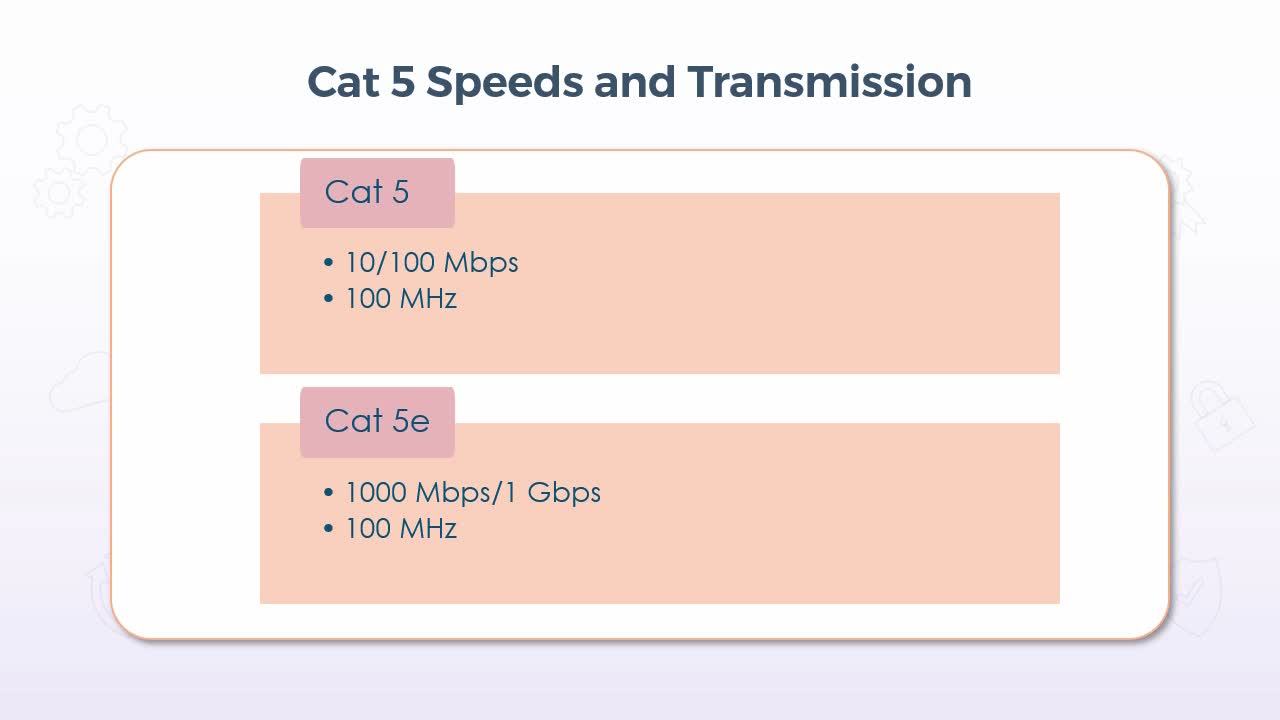
In this video, we'll specifically look at some of the limitations of wired Ethernet standards, including the speeds they can handle and some other considerations. But we'll focus on the most common cable standards at the time of this recording, of category 5, 5e, 6, and 6a. Now, with that, I should point out that category 5 would be quite rare these days, and also category 7 and 8 are available, but, that all said. Beginning with Cat 5 and 5e, 5 was only capable of supporting speeds of either 10 or 100 Mbps and used a transmission frequency of 100 MHz. So, even when compared to 5e, Cat 5 is considered to be quite slow. 5e increased the speed to 1000 Mbps or 1 Gbps, but still used a transmission frequency of 100 MHz.
So overall, Cat 5 with its top speed of only 100 megabits per second is not an ideal choice for most environments these days, particularly very large networks with very high bandwidth requirements. It might still be adequate in a home network, and I'd say that if you do encounter it, that would be the more likely location. In its unshielded implementation, Cat 5 is also somewhat prone to electromagnetic interference and crosstalk within the cable itself. So, Cat 5e or enhanced used improved materials to further reduce its susceptibility to interference and crosstalk, even in its unshielded format. But it is moderately more expensive than its predecessor, and that itself would be a very relative statement, because I would say that it's unlikely that you would be able to buy the original Cat 5 cable anymore at all. So, more appropriately at the time when environments were looking to upgrade, it was marginally more expensive.
But since it supported 10 times the speed, it was most certainly worth it. But even with its improvements over Cat 5 by today's standards, it is still somewhat out of date. Now Cat 6 also supported speeds of 1 Gbps, but it used an increased frequency of 250 MHz, which in itself didn't increase the speed at all, but made it a little less susceptible to interference, since there are fewer other types of devices or transmissions using that frequency. And both Cat 6 and 6a implemented a tighter twist in the internal wires, which further protected them from interference. 6a or augmented did increase the speed up to 10 Gbps and increase the frequency to 500 MHz, which again resulted in better resistance to interference.
But because of that tighter twisting I just mentioned, Cat 6 and 6a cables use more copper for the same length of cable as compared to Cat 5 or 5e, which ultimately translates into a shorter supported distance when using Cat 6 or 6a. In normal conditions, meaning when interference levels are within tolerance, Cat 6 and 6a can still be used over distances of 55 meters or about 180 feet. But that distance is reduced to only 33 meters or about 110 feet when interference is more prevalent. By comparison, Cat 5 or 5e could typically be used over distances of about 100 meters, but again, the improvements to the speed and the reliability for Cat 6 and 6a certainly make it a more viable choice in almost all of today's environments.
6. Video: T568A/T568B Wiring Codes (it_csap121_06_enus_06)
- outline the T568A and T5669B wiring standards
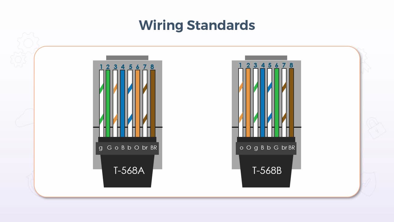
In this presentation, we'll examine the wiring standards for twisted pair cabling, which refers to the sequence of the individual wires inside a twisted pair Ethernet cable, which should be observed when crimping your own cables. Now there are two primary standards known as T-568A and T-568B, with the difference between them being only that 568B reverses the position of the green and the orange pairs. Now both of these are accepted standards, but in reality, the only reason they each exist is for backward compatibility with various implementations that were done differently by major vendors in the past. Overall, 568B is probably more common, but the US government,
[Video description begins] A slide titled Wiring Standards appears. It displays two types of cable samples: T-568A and T-568B. Both the cables contain a pattern of 8 coloured wires. The T-568A cable has the following pattern: wire 1 is 'g', wire 2 is 'G', wire 3 is 'o', wire 4 is 'B', wire 5 is 'b', wire 6 is 'O', wire 7 is 'br', and wire 8 is 'BR'. The cable T-568B has the following pattern: wire 1 is 'o', wire 2 is 'O', wire 3 is 'g', wire 4 is 'B', wire 5 is 'b', wire 6 is 'G', wire 7 is 'br', and wire 8 is 'BR'. [Video description ends]
for example, requires the use of 568A for all federal contracts. In terms of the colors themselves on the slide graphic we see letters that are used to indicate each color with a single uppercase letter used to indicate the solid color and lowercase letters used to indicate the matching color but with the white stripe.
So, for example, uppercase G indicates solid green, lowercase g indicates green with a white stripe. Now this remains consistent up until you get to brown where we see upper and lowercase br, which, of course, is used to distinguish it from blue. Now I'll admit that I don't entirely understand why the pattern is the way it is? In other words, why each solid color is not always next to its associated striped color? That is the case for each pair except orange in 568A and for all except green in 568B. But the standard is what it is, so who am I to argue? But I should also mention that if you are doing your own crimping, I'd say that it won’t be overly likely that the color scheme will be written directly on the connector as we see in the graphic here, because both standards use the identical RJ-45 connector. So, the manufacturer of the connector can't assume that the connectors they're selling will be crimped in one way or the other.
So, before you start, be sure to take note of which standard you're going to be observing, and maybe just print out a diagram of that standard to use as a reference. That said, where you would see the color scheme written would be on a patch panel where you punch down the bare wires. Patch panels typically tend to have both standards written one above and one below each row of connectors. So, for the 568 pattern itself, from pin 1 to 8, the sequence is, White/Green, Green, White/Orange, Blue, White/Blue, Orange, White/Brown and Brown. Then for 568B again from pins 1 to 8, it's White/Orange, Orange, White/Green, Blue, White/Blue, Green, White/Brown and Brown. Now those patterns are for what we would generally refer to as standard or straight through cables, meaning that they're used to connect computers to the data ports in the walls or directly to a hub or a switch, or any other networking device. But in some cases, you might need to connect a computer directly to another computer, in which case you need what's known as a crossover cable. Now this is because of the eight wires, four are used to transmit, and four are used to receive.
But since every network interface on every computer is built the same way, if you use a straight through cable to make a direct connection between two computers, you end up trying to transmit to the transmitters and receive from receivers, which clearly doesn't work. Hence, a crossover cable changes the pin configuration on one end, so that you end up transmitting to receivers and receiving from transmitters. So, in both 568A and B the pin configuration is the same, it's just the colors that differ. So in both cases from one end to the other, pin 1 connects to pin 3, pin 2 connects to pin 6, pin 3 connects to pin 1, 4 connects to 7, 5 connects to 8, 6 connects to 2, 7 connects to 4, and 8 connects to 5. As for the colors, the pattern on the end labeled in sequence from 1 to 8 in this graphic matches the sequence for their respective 568A or B standards just mentioned. But knowing this gives you a means to distinguish a straight through cable from a crossover cable, if it isn't otherwise written on the exterior jacket.
Simply examine each end side by side, because the colors are visible through the connector, they're almost always made from clear plastic. That set the entire exterior jacket of a crossover cable tends to be a different color than a straight through, but that's not a guarantee because many manufacturers are making straight through cables in many colors now. In my own experience, though, just for reference, straight through cables are most commonly blue, gray, black, or white, and crossover cables tend to be red or maybe yellow. But again, I stress that is by no means a standard, it's just what I've seen most often. Similarly, there is another wiring pattern which creates what's known as a rollover cable.
These would likely be less common than even a crossover cable, as they have a very specific use which is to connect your computer to the console port of a router or a switch to configure it. In terms of wiring, they implement the exact opposite sequence from end to end, so that pin 1 connects to pin 8, 2 to 7, 3 to 6, 4 to 5, 5 to 4, 6 to 3, 7 to 2, and 8 to 1. Again, with respect to the colors, you would simply want to be consistent on at least one end with either 568A or B, depending on what is in use in your environment. So again, these wiring standards should be observed, if you are tasked with crimping your own cables because anyone at any time could end up dealing with any cable. So, this simply helps to ensure compliance and consistency for your wiring.
7. Video: Video Cables (it_csap121_06_enus_07)
- identify video cables such as high-definition multimedia interface (HDMI), DisplayPort, digital visual interface (DVI), and video graphics array (VGA)
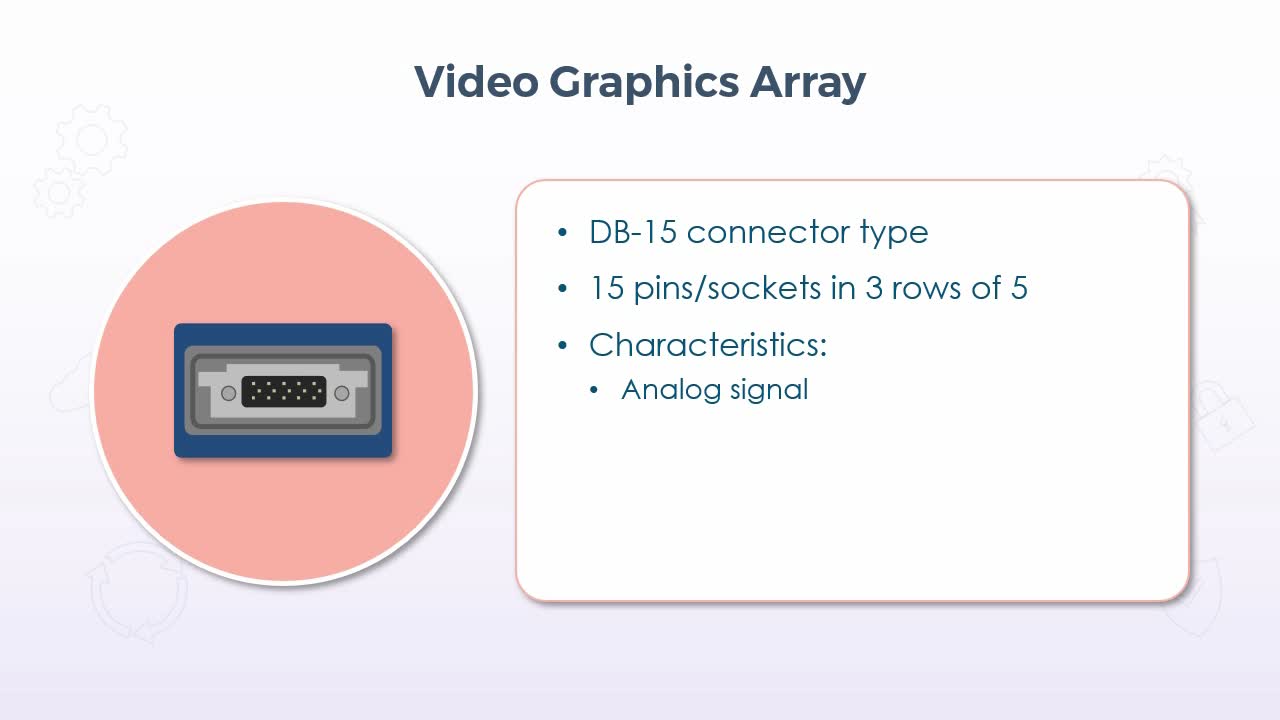
In this video, we'll take a look at several different video interfaces, beginning with video graphics array, or what's more commonly known as VGA. Now this interface has actually been around for a very long time. I started my career in the mid-1990s and it was already a well established interface then. But despite its age, it still remains fairly common even in today's environments because as improvements to the VGA specifications were released, it did provide support for enhanced resolutions right up to what we would consider to be high definition today.
The physical connector is a DB-15, meaning 15 pins or sockets in total, configured in 3 rows of 5. And the connector itself is usually blue or black. And in most cases, the connector on the back of a video card, or perhaps on the edge of your laptop was blue as well. Now the primary aspect of VGA is the fact that it's an analog signal, so it uses variances in electrical impulses to represent variances in colors, primarily red, green, and blue. So you may hear some people refer to this as an RGB connection, but because it's an analog signal, there is a consideration with respect to the length of the cable.
Now that's almost never an issue in terms of the distance between your computer and your monitor, but the longer the cable, the more degraded the signal will become, so this could certainly be an issue if you're trying to run a cable from your computer to a projector that was mounted on the ceiling in a large auditorium. That could be quite a distance, so by the time you reach the projector, the signal simply isn't very strong, so you might need some kind of amplifying unit. Now those are available, but, of course, at an additional cost. The next interface is known as DVI or Digital Visual Interface and, as its name indicates, it uses a digital signal.
But there are five different DVI connectors, DVI-I single link, DVI-D single link, DVI-I dual link, DVI-D dual link, and DVI-A. Each interface has one horizontal slot and a varying number of sockets. And while on the first glance, each one might look like it's very specific, some connectors are compatible with each other. For example, if we look at DVI-I single link versus DVI-D single link, the only difference is the four extra sockets around that horizontal slot in DVI-I. And the same thing applies for DVI-I versus DVI-D in dual link, meaning that if you have a DVI-D connector, it could still be used with a DVI-I interface.
And those four extra sockets simply wouldn't be filled, but it would still work, but only using the DVI-D specification. So some of them are compatible and essentially what it will come down to, is that if it fits it will work, but it will work at the specifications of whatever the PIN configuration is. Now the DVI-A connector, however, is not compatible with any of the other specifications. So then, with respect to the characteristics of the interface, single link versus dual link comes down to the amount of information that can carry and at what rate. So single link supports 3.7 Gbps at a rate of 60 fps, whereas dual link can support 7.4 Gbps at a rate of 85 fps.
Then the letter representation refers to the type of signal support where in fact, DVI-A does support analog signals for backward compatibility. DVI-D is digital signals only and DVI-I is for integrated meaning that it supports both. As for the speed characteristics, the single link would typically be adequate for almost any standard office environment. But if you were a 3D animator or doing intensive graphic design or gaming, dual link would be more appropriate, but would likely be more expensive. Now, despite some of its improvements over VGA. I have to say that DVI was not particularly common in most environments, simply because VGA continued to improve and was already much more prevalent. So, apart from the more exclusive applications just mentioned, such as graphic design and gaming, DVI didn't really catch on, so to speak.
Now, display port is a fairly new connector which allows you to connect video sources to your display. Now just to quickly clarify, that statement is no different than saying something like connecting your computer's video card to your monitor, but display port and I should also mention HDMI, which we'll see in just a moment, are both very commonly used for many different types of displays, including TVs, projectors, virtual reality headsets, specialized equipment monitors, and video walls, where there is literally just a wall of many TV's all working together.
Now, this was a specification that was defined by the Video Electronics Standards Association, or VESA, which is actually a very old association. But what it comes down to is that since it's a standard, it's not proprietary, so manufacturers don't have to pay any kind of licensing fee to put a display port on their device. In addition, display port uses packetized data transmissions very much like in Ethernet network, which can result in better flow control of the data. And display port is also capable of carrying audio signals as well. Lastly, High-Definition Multimedia Interface or HDMI is another digital video and audio interface that is similar to display port, but each has its pros and cons. And, in fact, HDMI and display port are currently in a battle if you will, similar to that of high definition DVDs versus Blu-ray, but each new version of either one, attempts to outdo the other. But at the time of this recording, display port does in fact have the edge, in terms of performance capabilities.
But in terms of overall implementation across all devices, I would say that HDMI is likely more common and it more than meets the needs of most users. But as is so often the case in these types of battles, there is always that subset of users who do require the highest levels of performance, so that's where you would likely find DisplayPort, and that's not unlike what I talked about just a moment ago with respect to DVI versus VGA. But at a more practical level, for most of us, in terms of the pros and cons, HDMI supports an audio return channel, which is very useful for connecting audio devices to something like your TV. So that no matter what input your TV receives, whether it's your TV receiver such as a PVR, your Blu-ray player, or your gaming system or whatever it is, the sound from all of them will simply be passed through your TV, to your audio system. So that you don't have to keep changing the input source for your audio. But display port supports the use of multiple displays over a single cable.
So, for the TV wall mentioned just a moment ago, or for people who need to monitor several screens at once, such as in a security office, you can just connect all of the display devices themselves in a daisy chained fashion, but a single cable from your source can drive them all. But also of note with respect to just HDMI, it replaces all existing analog standards. In other words, it is digital only. So, HDMI is not compatible with any kind of analog interface, whereas, display port is compatible with DVI with an appropriate adapter. And, of course, as we just mentioned, DVI-A and DVI-I supported analog video. As for the connectors for HDMI, there are in fact several, but the most common are Type A and Type C. Both have 19 pins and both have the same specifications in terms of performance. The only difference is the size. Type A would be what most of us would consider to be the standard connector that you would likely find these days on the output of your video card or on your laptop, or, of course, in the back of your monitor or your TV.
The cable itself has identical connectors on both sides, so there is no concern for the male versus the female, and it's similar in size to the original USB connector. But it borrows slightly if you will, from the D-sub connectors, in that, it's wider along the top than on the bottom, so it can't be inserted upside down on either end. Type C is also known as mini HDMI, and it's quite simply used for smaller devices where there's just limited space, such as on a tablet or even a mobile phone. So, like most things, the interface you choose usually just comes down to the implementation and/or what you already have. Again, these days I would say that HDMI is probably the most common overall, but you will almost always find situations where just about every other type of interface we talked about is still in use, so it's best to be familiar with all of them.
8. Video: USB Cables Types (it_csap121_06_enus_08)
- differentiate between USB, USB-C, USB2.0, USB3.0 cables
In this video, we'll discuss the Universal Serial Bus and its associated cables and connectors. Now, for starters, the interface itself has been around for quite some time now, certainly going back to the early days of my career in the mid-1990s, and it's used as an external serial bus interface. In other words, you don't find USB connections built right into your motherboard. It is entirely used for connecting external or peripheral devices to your computer, such as printers, your mouse and keyboard external storage devices, webcams, smartphones, gaming controllers, and many others.
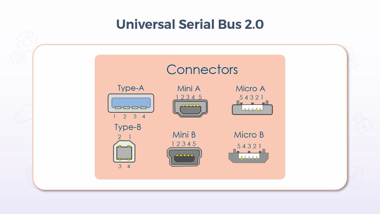
As for the connectors and cable specifications, that first comes down to the version of USB, and while there is a version 1, in terms of what you are likely to encounter these days, we'll focus on version 2 and higher. So for starters, the Type-A connector is probably what comes to mind
[Video description begins] A slide titled Universal Serial Bus 2.0 appears. It displays different types of connectors, namely, Type A, Type B, Mini A, Mini B, Micro A, and Micro B. The Type A connector has 4 pins labeled 1, 2, 3, 4 which are built at the bottom of the connector. Type B connector contains two pins 1 and 2 at the top and 2 pins, 3 and 4 at the bottom. The Mini A and Mini B connectors have 5 pins labeled 1, 2, 3, 4, 5 which are built at the top of the connectors. Similarly, Micro A and Micro B connectors contain 5 pins labeled 5, 4, 3, 2, and 1. They are shown at the top of the connectors. [Video description ends]
for most people when they think of USB. It has four pins along one side only, so it can only be inserted in one orientation. The port on the computer was almost always, if not always, female, and the cable would have the male connector, but the Type-A connector would be the most common type of connection at the end of the computer itself. Then the other end could be just about anything and in fact could often be very proprietary, such as a charger. But a very common example of what you might find on the other end would be the Type-B connector, which is most commonly used with printers. So, for example, a standard USB 2 printer cable would attach to the computer with the Type-A connector and to the printer with Type-B.
The mini connector also had A and B editions and as the name indicates, it was significantly smaller than Type-A and Type-B, and as such it was generally used for smaller devices. One of the most common being digital cameras. So, when you wanted to download pictures from the camera to your computer again, in most cases the A connection would be on the computer end and the B on the device end. The micro connector was smaller still than many and was commonly used for some smartphones, GPS devices, health monitors, and likely still some digital cameras as well. Once again with the micro A end typically connected to the computer and the B end to the device. In terms of specifications though, all were still using USB 2, so they could all transfer data at the same rate for example. The latest type of connector for USB is the Type-C, which is used most commonly with devices that support USB 3.1 or 3.2.
The connector itself has 24-pins and more on that in just a moment. And as mentioned, the Type-C connector when used with USB 3.1, supports data transfer rates known as SuperSpeed, which offers 5 gigabits per second and SuperSpeed+, which offers 10 gigabytes per second. And when used with USB 3.2, it increases the speed for each SuperSpeed rating up to 10 gigabits per second for SuperSpeed and 20 gigabits per second for SuperSpeed+. And it should also be noted that USB 3.1 does still support the use of the original Type-A connector of USB 2. But the interior of the connector on both the cable and the computer will typically be colored blue to indicate that it's using USB 3.1, as opposed to USB 2. But USB 3.2 only uses the Type-C connector. Now, with respect to some key differences with the Type-C connector, the physical layout itself, which comes back to the PIN configuration I mentioned a moment ago, is unique among all USB connectors in that of the 24 pins in total, only 12 are actually used, and it's the 12 pins that are either along the top or the bottom, which results in the orientation of the cable being irrelevant.
It can be inserted upside down or downside up, and it will still work perfectly. So, this is certainly nice for all of us who almost always attempted to plug in a USB Type-A connector, only to realize that it's upside down. It's also unique in that, if it is USB 3.2, which again, only supports the Type-C connector, then it's the same connector on both ends. So again, the cable orientation doesn't matter in any regard, end for end or up for down. Now, that said, that only applies when using USB 3.2 and exclusively the Type-C connector, but Type-C is also supported with USB 3.1, as is the original Type-A connector. So the data transfer rate will depend on the USB version, not the connector. For example, I have an external solid state hard drive on my desk right now. It's a Type-C connector on the drive end, but a Type-A connector on the computer end. So this immediately indicates that it's using USB 3.1 even though a Type-C connector is present. So the data transfer rate will only be a max of 10 gigabytes per second as opposed to 20.
However, this makes that same drive backward compatible with USB 2, so even though it will only work at USB 2 speeds, it will still work. So when it comes to the cable type that you want to use to connect a device to your computer, most notably, you should first determine the appropriate version, either version 2.0 or version 3.0. While it's been around for a while at the time of this recording, USB 3 is a relative newcomer, so it could easily be the case that your computer does not support USB 3. But again, it would come back to the sub category if you will, because as just mentioned, USB 3.1 does still support the Type-A connector, in which case, any USB 2 device could use a USB 3 cable and it would likely work, but only at USB 2 specifications. But if it's a Type-C connector and your computer does not have a Type-C connection, then you simply won't be able to connect it in the first place. But like almost any type of cable connection, there are, of course, adapters available but again, recall that as soon as you adapt the Type-C connector back to something like a Type-A,
then it is immediately using USB 3.1 at best, possibly USB 2. So just be mindful that you won't get the same level of performance. On a final note with respect to the Type-C connector, while USB 3.2 only supports the Type-C, there are some devices that use Type-C connectors but don't necessarily conform to USB 3.2 specifications. The most notable example of this is Apple's newest lightning cable which does use the Type-C connector, but since it's a proprietary cable, it does not necessarily have to conform to USB 3.2 specifications, but that's a fairly specific example. Most of the time a Type-C connector on both ends means that you can expect the performance level of USB 3.2.
9. Video: Peripheral Serial Cables (it_csap121_06_enus_09)
- identify peripheral cable types including serial and Thunderbolt
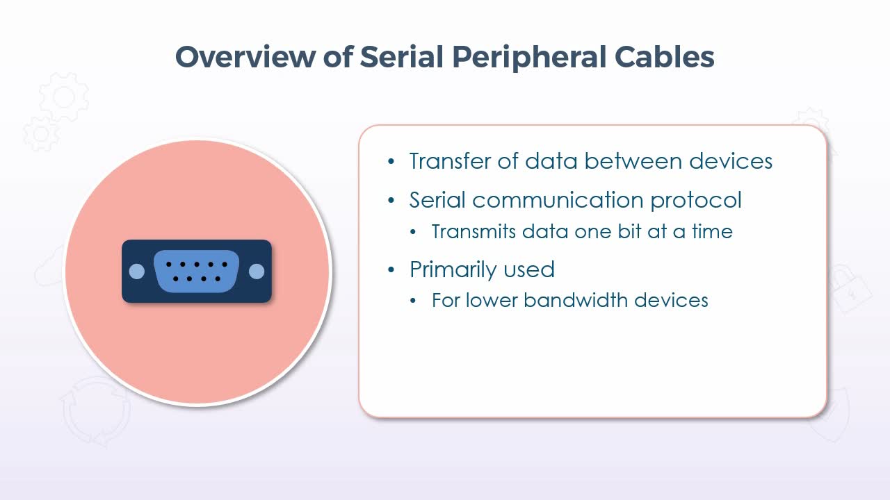
In this video, we'll discuss serial peripheral cable types as well as a much newer type, the Thunderbolt cable. Now these two types would effectively be at opposite ends of the scale in terms of performance, most notably because most types of serial cables are very outdated, but you may still see them being used for specific types of equipment, but that said, the traditional serial cable is, of course, used to transfer data between a peripheral device and a host computer, and they draw the name serial from the fact that they transfer data one bit at a time.
As such, they were primarily used for lower bandwidth devices, but because it was serial as opposed to its parallel counterpart, which transferred 8 bits at a time, they were better suited for transmitting data over longer distances because with parallel transmissions, it was often difficult to manage the timing of the data across all eight channels, so the longer the distance, the greater those timing issues became. Now there were several defined standards for serial transmissions that we'll see in just a moment, with each one typically defining varying transmission properties, such as the speed and distance over which data could be reliably transmitted. So, beginning with some common examples of where you might have encountered serial cables, one example was to connect an external modem to your computer.
Now with respect to any younger viewers in the overall picture, high-speed Internet, particularly at home, is relatively new. When I started working as an IT professional, there was effectively no such thing as high-speed Internet. We had to use very low-speed modems over our phone lines to establish a dial-up connection, to our Internet service providers. Now there were internal modem cards that could be installed, but external devices were a little easier to work with, so the connection between the modem and the computer would have been using a low-speed serial cable and by low speed I mean very low speed.
By today's standards, a network that operates at 100 MBps would still be considered to be slow. The type of serial cable commonly used for external modems, may have only supported 9600 bps, so not even 10 Kbps. Now in some cases that kind of speed is more than adequate because devices such as keyboards and mice barely transmit any data at all, so it's not as though serial cables didn't have their use. But even though they would still be more than adequate even today for very basic devices. The prevalence and performance of USB replaced those connections for almost all peripheral devices.
So as for some of the serial transmission standards mentioned a moment ago, the RS-232 cable was perhaps the most commonly used, and in fact, this is the specific type that only supports 9600 bps over a distance of about 15 meters, or just under 50 feet. The RS-422 specification made significant improvements to the speed supporting in fact up to 10 MBps over about 12 meters or just under 40 feet. And it could also handle distances of up to a kilometre, but significantly decreasing the speed as the distance increased. Then RS-485 didn't do much in terms of increasing the speed, but it was capable of supporting many devices in a daisy chained manner, or what's also referred to as a bus topology. Now, while I would say that it's very unlikely that you would encounter any of these cable types, in most standard computing environments.
You may still see all of them in use for specific equipment used in a variety of industrial environments. So turning to the newer side of things, the Thunderbolt cable was developed and introduced by Apple and Intel, and it's capable of supporting very high-speed resolution displays and high performance data transmissions over a single port which is also capable of supporting multiple devices in a bus topology. Now, while it is most commonly used with Apple devices, the partnership with Intel means that it's not entirely proprietary to Apple, so other platforms do offer support for Thunderbolt devices. As for performance and specifications, Thunderbolt offers up to 40 Gbps data transfer rates in its most recent version, and it's also bidirectional.
Meaning that it can transmit and receive at the same time, which of course would depend on the application. But that speed is supported in each direction separately. In other words, it's not cut in half to 20 Gbps each way when communicating bidirectionally. It's still 40 Gbps each way. And with respect to those applications, Thunderbolt supports audio, data transfers, power transfers for charging and video data all over a single port if needed, resulting in far fewer cables for the multitude of devices that many mobile users have, which then translates into uses such as more powerful and better performing graphics, much faster compression and encoding when data is being written or accessed, and much faster data transfer rates, such as when burning to something like a DVD or a Blu-ray.
In short, technologies such as Thunderbolt and, of course, USB have effectively rendered the serial cables of old almost entirely obsolete, again, with the exception of those specific uses, such as for industrial equipment. So it's still important to know their specs if you find yourself working in such an environment, but for the personal computing world, serial cables are all but extinct.
10. Video: Hard Drive Cables (it_csap121_06_enus_10)

- differentiate between serial advanced technology attachment (SATA), small computer system interface (SCSI), external SATA (ESATA), and integrated drive electronics (IDE) hard drive cables
In this video, we'll examine some common types of cables and interfaces that are used to connect hard drives and other storage devices to your computer, along with some of their performance characteristics. So the first type is what's known as IDE, which stands for Integrated Drive Electronics. Now, if you had a desktop computer back in or around the 1990s into the early 2000s, I would say that it would have been very likely that it was using IDE cables to connect the storage devices to the ports on the motherboard and due to the physical shape of the cable which was very flat and wide, it was often referred to as ribbon cable and most had three connection points. Two that could connect to your devices and one that connected to the motherboard.
Now the most common implementation for the two devices was one for the hard drive and one for the CD-ROM or DVD drive, but you could have two hard drives on one cable if preferred. And in fact, most motherboards had two IDE connections. So in fact you could have four devices in total on two cables in any combination of hard drives and/or optical drives. But, of course, you needed at least one hard drive. Now there were two different sizes, or more appropriately, widths of the cable. The 34-pin was used for the old floppy disk drives, which are all but extinct these days, and the 40-pin cable was for hard drives and optical drives. Since they were physically different sizes, there was no concern for using the wrong cable for the wrong device, but they did look very similar, but again, the 40-pin cable was physically wider by 6 wires. Now, we'll see the interface specifications in just a moment, but IDE, like many other storage interfaces, had several different iterations and versions, but most common was known as Enhanced IDE or EIDE.
But you may have also heard Fast ATA, where the ATA stands for Advanced Technology Attachment, Ultra ATA, and Expanded IDE among others. With each different specification offering varying improvements to the interface, but the E for enhanced was more of a categorical classification, whereby any iteration that provided transfer rates better than the original IDE could be considered to be enhanced. For the most part, what you were looking for was simply the data transfer rate, because all IDE devices still used the same interface in the same cable, so there weren't a lot of concerns with respect to compatibility with the exception of what your motherboard would support.
In other words, you wouldn't have wanted to go out and spend money on a faster hard drive than what your motherboard would support. It would still work, but only at the lower data transfer rate. I should however mention that enhanced IDE also introduced support for larger capacity drives. Some of the younger viewers out there may be surprised to learn that the very large hard drives that we use today were not supported back then. Most IDE hard drives were under 4 gigabytes, but EIDE introduced support for drives up to 8.4 gigabytes. But that's still substantially smaller than what we used today. So with respect to the specifications, the most important value for almost every implementation other than the capacity was the speed.
So again, this would vary depending on the iteration of IDE, but among the later revisions, speeds for read operations were 100 and 133 MBps, while for write operations speeds were considerably slower. Coming in at 66, 33, and 16 MBps. Ultimately, when purchasing a new device, it was generally just a matter of taking note of the specs your motherboard would support, then getting the fastest model, but of course more speed also meant more cost. Now there's one particularly important thing to note here when it comes to the data transfer rates of hard drives. This is about the only instance where that rate is expressed in MBps, and that's indicated by the use of the uppercase B.
By contrast, if we're talking about network speeds that's always expressed using mega, or gigabits per second, which is indicated by the use of a lowercase b, so be on the lookup for the case of the b. It is important because, of course, there are 8 bits in a byte, so a value such as 100 MBps is the same as saying 800 MBps and 133 MBps. In fact, does go over 1 Gbps. Now those might not seem like overly fast speeds by today's standards. But recall that the IDE specification was commonly used back in the 1990s, at which time network speeds were only around 10 MBps. So by comparison, even what we would call very old IDE devices were considerably faster than network speeds at that time.
The contemporary to IDE was the Small Computer System Interface or SCSI, which was virtually always pronounced scuzzy. Now while SCSI almost always outperformed the IDE interface. It wasn't very commonly used in desktop PCs, but it was very common in larger, more powerful network servers. Primarily due to the fact that more devices could be supported on a single SCSI cable. In fact, up to 8 in total in its original release, then later increased to 16. Now one of those 8 or 16 connections had to be on the interface card or directly onto the motherboard itself, but where IDE could only support 2 hard drives plus the motherboard connection. SCSI could support 7 or 15 plus the motherboard connection, so this gave servers much more storage capacity, because recall that back in those days hard drives themselves had a much lower capacity, so the ability to host so many more devices, allowed servers to store far more data than desktop systems.
In addition, you could also install more than one SCSI interface card onto the motherboard. So for example, if you had even just 2 controller cards using the later specification, you could have up to 30 hard drives in a single server, and if needed keep adding more cards. As long as you had the physical space to support the drive themselves. As for the cable for internal drives, it was a ribbon style cable still but wider again than IDE, having 50, 68, and 80 pins depending on the version. And SCSI also supported external devices well before we were using them regularly over USB connections, in which case 50 and 68 pin cables were used.
Something else that should be mentioned that distinguished SCSI from IDE was the ability to hot-swapped a drive. In other words, you could remove and/or replace a hard drive without shutting the system down. Again, this is very useful for a server with many hard drives, because the more drives you had, the more likely it was that any one of them might fail. So being able to replace the drive without shutting down the server meant no disruption of service other than perhaps the time it would have taken to restore a backup of the data that might have been on a failed drive, but the server itself could remain running still servicing other client requests. So as mentioned, SCSI was released in several revisions as well, which were effectively just numbered 1, 2, and 3.
With each revision introducing improvements and enhancements to features such as the frequency of data transmissions and how many bits could be transferred on each cycle. But Revision 1.0 was quite slow by comparison to the later revisions, but it's also very old. So it only supported an overall throughput of 5 MBps, and also take note that with SCSI and in fact the later interfaces throughput was not measured by read versus write speeds. Rather it's just an aggregated value that more or less revert to both operations, effectively averaged out if you will. So Revision 2.0 increased the frequency and the number of bits per cycle, significantly resulting in what was known as Fast/Wide, where the Fast refers to the increased frequency and the Wide refers to more bits per cycle.
Achieving a significant jump in throughput all the way up to 320 MBps in its latest form. So now we're into the gigabit range, that's about 2.5 Gbps. And again, this was still 20, 25 years ago. Now, within each revision there were incremental improvements, so Revision 2.0 didn't immediately jump to that level. Initially, it came in at about 20 MBps, but ultimately increased to 320 and Revision 2.0 is also where the support for 16 devices total was introduced. Ultimately, Revision 3.0 is where a SCSI more or less finished with support for longer cable runs which allowed for more space between drives and facilitated better airflow and cooling.
And by its latest iteration it supported throughput of up to 640 MBps, or a little more than 5 Gbps. Now, there may still be many servers using the SCSI interface, but in the early 2000s along came the Serial Advanced Technology Attachment interface, or more commonly, Serial ATA or even just SATA or SATA, depending on preference, which was the successor to the previous parallel ATA interfaces, which included IDE. Now, despite those interfaces being parallel, which means they can transfer 8 bits at a time as opposed to just one at a time. Hence the term serial. A lot of resources were required to ensure that all 8 bits arrive at the exact same time, which they often didn't, resulting in a lot of retransmissions and quite simply enhancements to the overall technologies, architectures and protocols involved allowed for serial interfaces to surpass the capabilities of their parallel counterparts.
Hence the speeds we're seeing these days with interfaces such as USB, which is the Universal Serial Bus not parallel. In any case, the Serial ATA interface immediately outperformed IDE with its first release and rivals SCSI with its latest. So it most definitely became the standard for desktop computers. But as mentioned, many network servers could still be using SCSI. Also of note was a complete redesign of the cable. I realized that it's a little difficult to tell from the graphic here, but the cable itself is significantly smaller than all the types of ribbon cable.
It's only about a centimeter wide or less than half an inch, which again makes for much more space within the case, and promotes better airflow and the connectors are only about the size of a type-A USB connector, and much like the USB connector, they use a single slot and socket as opposed to many individual pins, which eliminates the possibility of bending or even breaking the pins on IDE or SCSI devices, and the connector was keyed so that it couldn't be attached upside down. In Revision 1.0, Serial ATA offered a throughput of 150 MBps, again faster than any addition of IDE, and also supported the cable length of up to 1 meter or a little over 3 feet, which was typically not an issue in a desktop system. But if you were putting together a server with Serial ATA drives, then this again afforded you more space and better airflow. Then Revision 2.0 supported up to 300 MBps, also, over a 1 meter cable. And Revision 3.0, as mentioned rival's the fastest SCSI revision at 600 MBps, still over a 1 meter cable.
Lastly, it should also be noted that Serial ATA also supports hot-swappable devices and many more devices than IDE, but for desktop computers most motherboards will still likely only have 2 or maybe 4 inherent connections, but you can also buy a Serial ATA controller card that can be inserted just like a SCSI controller card, allowing you many more connections. Although with Serial ATA, there is only ever one connection per drive, so you can't host multiple drives of 1 cable, but the connectors themselves are so small that 8 or more connections could easily fit on a single controller card. So as always, at least with respect to purchasing something new or replacing something old, it will come down to what you want versus what your motherboard will support. So just be sure to verify everything before making a purchase.
11. Video: Common Adapter Types (it_csap121_06_enus_11)
- differentiate between adapters such as DVI to HDMI, USB to ethernet, and DVI to VGA
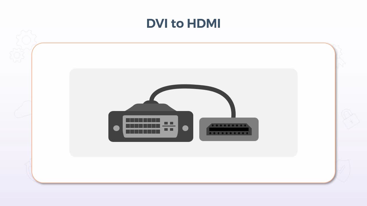
In this video, we'll take a look at a few examples of some common adapters, which, of course, allow you to convert 1 type of connector to another. Now, before getting into that, let me first state that there are a tremendous number of adapters available, but that certainly doesn't mean that every type of interface can be adapted to every other type. There are still limitations and inherent incompatibilities that exist, so always be mindful of that.
And verify that an adapter does in fact exist for your particular situation before you make any purchases. That said, the first example is a DVI or digital visual interface to HDMI or a high definition multimedia interface, which can be used to adapt a connection from a video output source such as your video card to a different type of input on a display device such as a monitor. So, looking at an example of when you might need this adapter, well, quite simply, it would be required if your existing video card or other output source is DVI, but the input on the display device, such as a monitor is HDMI, or the exact opposite could be the case.
So, perhaps you have an existing desktop computer with a DVI based video card and a DVI based monitor, but then you decide to switch to a new laptop. But you'd like to use your existing monitor as a secondary display for the new laptop, but the laptop only has an HDMI interface. Hence, a DVI to HDMI adapter can be used as these two interfaces are compatible with respect to the ability to adapt from one to the other. But I should point out that DVI is not capable of carrying audio whereas, HDMI is. But in this example, audio would not be an issue. Another very commonly used adapter is USB to Ethernet, which is often used with newer laptops equipped with solid state drives.
Or it just might have an overall thin profile. Due to that thin profile, there is often no wired Ethernet connection available. In fact, that's the case with my own laptop that I'm using right now. But, of course, it does have USB ports, so this adapter eliminates the need for an RJ-45 connector to be built into the laptop, which, of course, saves space and promotes the smaller, lighter form factor. Using this adapter also comes with some considerations, most notably the speed. For example, the wired Ethernet network itself may be operating at 1 gigabit per second, but if your USB interface is using the older USB 2 specification, then its maximum speed is only 480 megabits per second. So, it will still work, but only at the lower speed. If however, your USB interfaces version 3, then it will be fully capable of supporting that speed.
There may also be use cases for USB to Ethernet for mobile devices, including tablets and even some smartphones. For example, many newer Android devices are equipped with a USB-C interface, so a wired Ethernet connection could be used for these devices, but it will come down to what the device itself supports. So be sure to verify that your device will support the use of this type of connection before you purchase. And in most cases, it would also be recommended that you disable the wireless interface, before attempting to use a wired connection. Similar to our first example of adapting DVI to HDMI, you can also adapt DVI to VGA. Now, while both of these interfaces would be considered to be out-of-date by today's standards, when DVI was starting to become more common, there were situations wherein it was either the computer or the monitor that might have been upgraded, but perhaps not both.
So, for instance, if you had purchased a newer monitor for an older computer, you would need to adapt from the VGA output to the DVI input. If however, you bought a new computer for use with an older monitor, then, of course, the exact opposite would apply. So, you just needed to be mindful of the gender of each end of the adapter. The output connector on video cards and or laptops were usually female and the input connector on the display device, such as a monitor was usually female. Now, the reason why I'm pointing this out here and not for some of the other adapter types is because newer cables such as HDMI are the same on both ends, so gender isn't a concern, but both DVI and VGA cables had different genders on each end.
That said, regardless of the direction of adaptation, a DVI to VGA adapter provided backward compatibility, so that you could upgrade just one component as opposed to both. But do take note that in this particular case, VGA is an analog signal, meaning that you had to have a DVI interface that was compatible with analog, which included DVI-A, where the A stands for analog, meaning that it is supported. DVI-I where the I stands for integrated, meaning both digital and analog are supported. But DVI-D is digital only and it would not be supported for use with an analog signal. Other considerations when adapting VGA to DVI is the image quality. In short, DVI is capable of higher resolution support than VGA, so the signal is only ever as good as its weakest link, which in essence refers to the adapter itself. So as an example, if your monitor can fully support 1080p at 1920×1080 resolution, once adapted to VGA, it may drop to 1024×768. So again, it's just something else that should be noted before purchasing.
Now that's only one example. Both interfaces can support resolutions higher than that, but in most cases the conversion process itself results in a lower quality image. So ideally, in this case at least, the adapter should be used as more of a temporary solution. Native connections and cables will always provide the best quality overall.
12. Video: RJ-11 and RJ-45 Connectors (it_csap121_06_enus_12)
- differentiate between RJ-11 and RJ-45 connectors
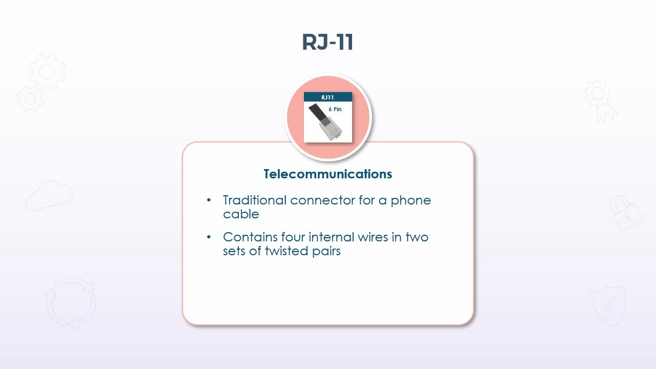
In this presentation, we'll examine the difference between the RJ-11 and RJ-45 connectors, which do look somewhat similar to each other, but they were used with different cables and for different purposes. So beginning with the RJ-11. This connector was used almost exclusively for telecommunications equipment or more simply stated, what most of us would recognize as a standard phone line for use with traditional landline phones. The cable itself only contained 4 internal wires configured in two sets of twisted pairs, so it did still use the twisted pair approach, just like standard Ethernet cable, and in fact just quickly coming back to the category specifications for these types of cables.
Phone line cabling is in fact classified as category 2. As for its characteristics, the RJ stands for Registered Jack and that applies to both the RJ-11 and RJ-45 connectors, but the connector itself is physically smaller than the RJ-45 using what's known as a six position or sometimes referred to as 6 pin 4 connector configuration, which is often shortened to 6P4C. Now this simply meant that there were actually 6 individual pins in the connector itself, but the cable only had 4 internal wires. So only 4 of the 6 were used. The additional 2-pins were there, more or less for forward compatibility purposes or other applications that might use the same connector but with different cabling.
But the most common applications for the RJ-11 connector in a 6P4C configuration, where standard phone lines, modems, and DSL Internet, but the cable itself with that connector was limited to a maximum bandwidth of only 24 Mbps. So it quickly fell out of use for DSL, when DSL itself surpassed that speed. So the RJ-45 connector then is what we find in use with Ethernet cabling used on virtually all categories of twisted pair cabling since at least category 5. The cable itself contains 8 internal wires configured in four sets of twisted pairs, so the connector itself, while similar in appearance to an RJ-11, is physically wider by 2-pins. Since there are 8 wires and 8-pins or connectors in use in the RJ-45 and its associated cabling, its configuration is referred to as eight position or 8 pin 8 connector or 8P8C.
And this is used almost exclusively for data applications on Ethernet networks. Although I should point out that many phones, particularly in an office environment these days, also use RJ-45 connections and Ethernet cable because their voice over IP phones. So in essence there just like any other host on the network, but they don't use traditional phone lines, nor the RJ-11 connector. That said, some models may have both so that it can be used in either situation, standard landline phones or voice over IP applications. The connector itself on the most current category of Ethernet cabling can support a maximum bandwidth of 10 Gbps at the time of this recording. So to quickly summarize the difference between the two, the RJ-11 is most commonly found in use with cabling for phones, modems, and DSL connections has a maximum bandwidth of only 24 Mbps, and its physical shape is fairly compact.
A little more square-shaped overall and has 6-pins, and the RJ-45 connector is almost always found in use with twisted-pair Ethernet cabling as a maximum bandwidth of 10 Gbps on ethernet networks, and has a more rectangular shape, that is larger than the RJ-11 and has 8-pins. So again, they're easily distinguishable from each other, both in terms of physical appearance and performance characteristics.
13. Video: USB Connector Types (it_csap121_06_enus_13)
- differentiate between USB connector types including microUSB, miniUSB, and USB C
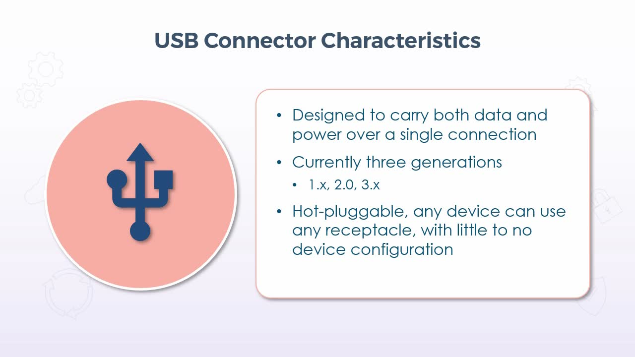
In this video, we'll examine some of the characteristics for the various types of connectors in use with USB cabling. Now, for starters, USB itself is designed to carry both data and power over a single connection, and there are currently three generations which effectively are 1, 2, and 3. But both 1 and 3 have subcategories, if you will, which is indicated by the .x. Now all USB devices are hot-pluggable, meaning that any device can use any receptacle, with little to no device configuration and nothing has to be powered down and/or rebooted. You can plug the device in, and it really should be detected immediately and again in most cases configured automatically.
But there are several different variations when it comes to the connectors, so this will depend on the version, of course, but the standard types do include what's known as Type A and Type B. And in just about every case, Type A is what you would plug into the computers interface and type B would be what you would plug into the device itself. So a common example would be something like a printer or a scanner or a multifunction device. Type A would be the end that plugs into the computer. And Type B would be the end that plugs into the printer itself and they are physically different from each other. So there's no way that you could plug in the wrong end of the cable into either the computer or the device. It has to go in, in a particular manner. Now there were some smaller implementations of these connectors that initially were introduced with USB version 2 known as the Mini.
And once again, we have two different types. There is the Mini A and the Mini B, and the same applies the A end connected to the computer, while the B end connected to the device. Now it is difficult to see from this graphic, but the Mini A connector has 245 degree angles if you will cut on the bottom. So, it has a little bit of a narrower bottom than the top, whereas Mini B was pretty much the same across the top and the bottom in terms of the size. But as their name indicates, both of these were physically smaller than their original Type A and Type B counterparts.
So these were most commonly found in cameras or smaller devices where space was a little more limited. Now, from that point we were introduced to the Micro connector and once again there were two types, the Micro A and the Micro B, and once again the same thing applied. A was the computer end, B was the device end, and these were physically smaller even still than Mini. So you would most commonly find these for some of the newer mobile devices that were still fairly small, such as cellphones, GPS devices, or personal digital assistants. And once again it's a little bit difficult to tell from the graphic here. But the Micro A connector was fairly symmetrical in terms of its shape, whereas the Micro B connector had those similar 45 degree cut-offs if you will on each end.
So that it could be distinguished from the other end. From that point, we saw Micro B which was only available for use with USB 3.0 devices, so it was not backward compatible with USB 2 or 1 devices, but it was designed primarily for the current high-speed requirements of newer devices. So in essence, it was certainly a physically different cable, but it was more so the speed of these devices that was the concern. The older types of cables simply didn't support the data transfer rates that were required. And that led us into the Type C connector which is the newest USB interface, and it comes in a symmetrical oval shape that is reversable. Meaning that it no longer mattered if you were attempting to plug it in upside down or downside up, it works in either configuration, and it's also the same connector on both ends, so it's reversable end for end as well as up or down, which makes it very convenient.
It's comparable in size to that of Mini. So it's suitable for many smaller devices as well, and it supports the highest speeds currently available (up to 10 Gbps). So I think moving forward, you will certainly see a lot of devices using Type C until the next version comes out, but Type C at the moment is certainly very convenient, very fast and very suitable for all types of devices. Now, one last thing that I should mention is that the Type C connector is only available for USB three devices. So it does not work with anything prior to that version, but that said, there are adapters available that likely would allow you to use it with a USB 2 device, but it would only then work at the specifications of USB 2. So it would certainly be slower, and it might not carry the same amount of power as well, but at least it would function.
14. Video: Fiber Optic Connectors (it_csap121_06_enus_14)
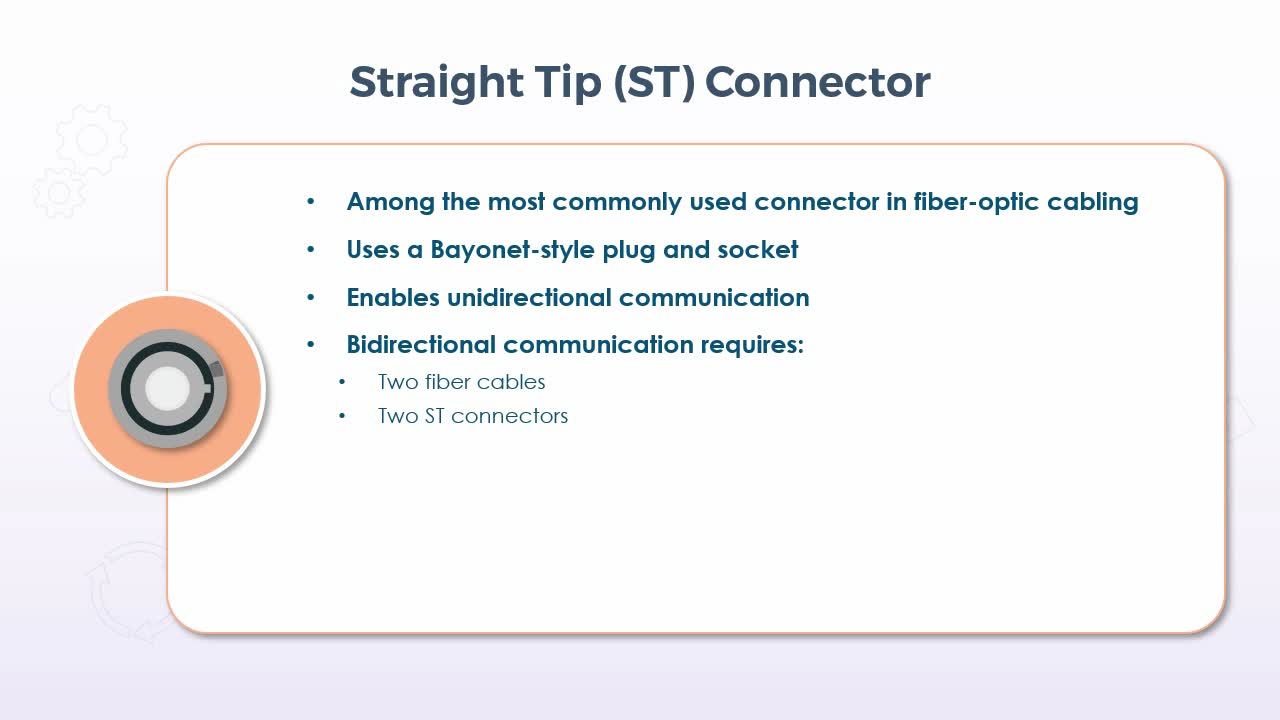
- differentiate between straight tip (ST), subscriber connector (SC), and Lucent connector (LC)
In this presentation, we'll discuss the different types of connectors in use with fiber optic cabling. Beginning with the straight tip or ST connector, which is among the most commonly used type of connector in fiber optics and uses what's known as a Bayonet-style plug and socket, due to the fact that it is inserted then twisted to lock it into place. Now this provides only for unidirectional communication, meaning that for bidirectional communications, two cables and two connectors on each end are required. Now, that said, in many cases each unidirectional cable is still enclosed within a single outer casing, so that from our perspective there is only a single cable, but there would still be two connectors at each end.
The design of the connector itself is to ensure proper alignment of the wire at its termination points. Because, of course, we're dealing with beams of light with fiber optic transmissions. So, in essence they ensure that the light leaves and enters the communicating devices in a straight line, so to speak, because as the light travels down the cable it reflects and refracts. So, the connector is designed to stop all of that bouncing around if you will, and to ensure that no light is lost as it passes from the cable to the device. ST connectors are suitable and often used for both single-mode and multi-mode fiber communications. The next type is what's known as the subscriber connector or SC, and despite the fact that the C stands for connector, it is very likely that you'll hear this referred to as the SC connector. And due to the square shape of the outer shell, it's also commonly referred to as the square connector, but then, of course, SC still applies.
Now it attaches using a simple push-pull motion that snaps in when it latches securely and its key so that it can't be connected in the wrong orientation. SC connectors and cables also only provide for unidirectional communications over one cable. So again, for bidirectional communications, two cables and two connectors on each end are required. But again, in many cases the two separate cables are bound together into one cable with two connectors on each end. And I should mention that really this is the case with all fiber optic cabling. When you're sending light down a cable, it is always only ever in one direction.
Trying to send light in two directions at the same time on the same cable would only result in the light waves interfering with each other, which would render the data unusable. Features of the SC connector include a generally trouble-free implementation, in that the connectors tended to be a little more resistant to damage than ST connectors, because they actually had a spring-loaded Ferrell, which sometimes could fail. And they were a little less expensive than the ST connector, while still providing a robust connection and precise alignment, resulting in minimal signal loss, if any. That all said they are a relative newcomer, at least compared to the ST Connector, so it remains likely that you'll still see ST connectors being used.
But you might see more SC connectors in newer implementations. Lastly, the lucent connector or LC is a significantly smaller connector, only about half of the size of the SC. And it combines the connectors for each unidirectional cable into a single housing. So, two separate connectors no longer have to be present on each end of the cable. Lucent connectors are becoming very widely used in many implementations, including telecommunications networks, cable television services, fiber-to-the-home, which typically combines Internet TV and phone, standard local area networks and large data processing networks. That said, the adoption of the lucent connector has been a little slow in some cases because it's a proprietary connector developed by Lucent Corporation. Therefore, manufacturers have to pay a licensing fee to use it. But in terms of benefits, its smaller size means that more connections can be implemented on any given device, which in turn can translate into cost savings.
Perhaps not so much with respect to the connector itself, but for example, a switch that is using the larger SC or ST connectors might only support 24 connections. But with the LC connector on the same size switch, it might support 48 connections, so fewer devices would have to be purchased. Plus, the LC connector also uses the more standard push to click latching system, which is now generally regarded as more reliable than the Bayonet-style of the ST connector. And since both directional cables terminate within the single connector, if the cable had to be moved, only one connector has to be relocated as opposed to two, which can ultimately translate into increased longevity as well.
15. Video: Punch Down Blocks (it_csap121_06_enus_15)
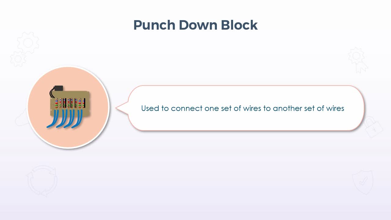
- provide an overview of punch down blocks
In this video, we'll take a look at to the punch down block which certainly would not be thought of as a standard type of connector in terms of having a distinct object at the end of a cable that then just gets plugged into some kind of prefabricated receptacle. Rather, they provide a means to connect cables together using the bare wire ends. Now the wires themselves are connected in the same manner as a patch panel in that individual wires of twisted pair cabling are pushed or punched down into a small slot. But instead of those wires then leading to a receptacle such as an RJ-45 style connector on the front of a patch panel. There is just a matching set of punch down connectors either next to or across from the original row where the corresponding wires of another cable are attached.
Now there would be several different implementations for a punch down block, for example, in a new construction, there might be pre-installed wiring that connects to various types of communications equipment. So then you as the eventual tenant just connect to the appropriate wires that suit your specific needs with respect to the equipment you need to use. Or maybe you simply need to extend the length of existing cable runs to facilitate changes to your environment, such as relocating your central wiring room to a new or a larger location to facilitate growth. So let's just use that example to help visualize things a little bit easier. Imagine that you're standing in the middle of your old wiring room. All equipment has already been relocated to the new room, so you're left with a bunch of cables with bare wire ends just hanging there.
Now new cables have already been run back from the new wiring room, but they're also just hanging there, also with bare wire ends. So you now have to connect those bare wire ends to each other for each cable. Well to do so, you simply punch down the old wires into one side of the block, then do the same with the new wires on the other side. Making sure that you connect the corresponding wires to the correct slots, but that's it. You then connected those two bare wire ends once they're both punched down, and you've effectively extended the cable runs. Now punch down blocks have been in use for quite some time because they've been used for several different types of wiring, including telephone systems, data network wiring, and other low voltage wiring.
So they aren't used only with Ethernet cabling, and the current implementation is what's known as a 110 punch down block, and it's a more up-to-date version that for the most part is the successor to what's known as the 66 block. They're more compact than they have a more efficient configuration. So that more connections can be made in less space. So as for the wiring scheme, the 110 punch down block allows for 25 pairs of wires to be connected in each block or bank of connectors.
[Video description begins] A slide titled 110 Punch Down Block Wiring appears. It displays a list of items under the following column headers: Pair, Figure, Tip, and Ring. [Video description ends]
Then there could be many individual banks of 25 pairs on any given strip base piece or rack mounted unit. Each block of 25 pairs is maybe about 2 inches wide and maybe 5 or 6 inches long with one row of 25 connector slots along one of those 6-inch sides and 25 corresponding connector slots on the opposite side, with the cable running through the space in between each row.
So then you can have as many individual blocks attached to that base strip as you need, but of the 25 connectors on each side, you might only connect the wires for the appropriate cable type that you're working with. So if, for example, you're working with, let's say category 6 twisted pair cabling for an Ethernet network, then only the first 8 connectors would be used on either side, which matched the color configuration of twisted pair cabling. For example, white and blue, white and orange, white and green, and white and brown. Then simply connect the other cable to the other side with the matching color configuration.
If you also happen to be working with other cable, then in fact they can also be connected within the same block, because each connector on any given side mates only with its counterpart on the other side, and I should also mention that in fact there is a single 25 wire cable, meaning that all 25 wires are simply included within a single outer casing which could be pre-installed on either side, which then makes the connections to the pre-installed devices, for example. Then you can just leave it to the eventual tenant to connect whichever types of wires they happen to need to connect to those devices. If it's just being used to an extend an existing cable run though, there wouldn't be anything pre-installed. But again that just comes down to the circumstances. So as mentioned, each bank or block accommodates 25 pairs or 50 wires in total.
So if you are pre-installing that single 25 wire cable, you simply follow the wiring scheme as indicated. Connected devices on the other end of the cable, then leave it to the tenant to connect whatever they like. But the color scheme is a standard and should always be followed when prewiring a punch down block. Again each different set of colored wires are simply used for different types of wiring or different types of devices. But cables such as category 5 and up for Ethernet and possibly category 2 for analog voice would still be among the most commonly used. Finally, in terms of the types as mentioned earlier, there is a 66 block which was most commonly used with the original analog phone systems. A BIX or B-I-X block is a proprietary type developed by Nortel Networks. So it's typically found only in use with their equipment.
A Krone block is effectively the European implementation, and, of course, the 110 block effectively supersedes the 66 block. Again, the type of block being used, and its implementation will vary. But ultimately, the block itself simply gives you a means to connect 2 bare wire ends to each other to complete a connection between those wires. So for any situation where this is required, the punch down block is the solution.
16. Video: DB-9, Lightning Ports, and F Connectors (it_csap121_06_enus_16)
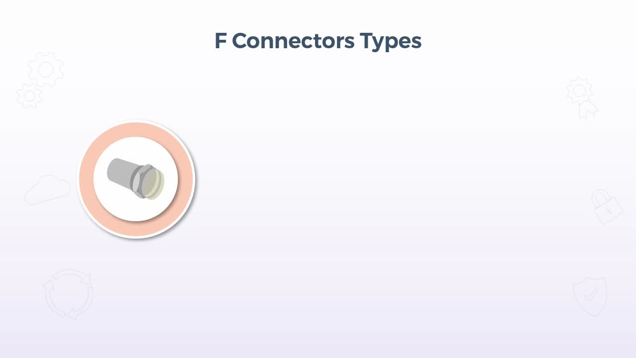
- provide an overview of DB-9, lightning ports, and F connectors
In this presentation, we'll provide an overview of some specific types of connectors that are used most often with specific devices or cable types, including F connectors, DB9, and Lightning. Now, beginning with the F connector, these are most commonly used for video distribution or when connecting to specific video devices, such as security cameras. The cable in use with an F connector is coaxial cable, which for those of you who don't have fiber into your home for Internet, is likely the cable that is providing your standard television service. The connector itself comes in a few different varieties, including twist-on, crimp-on and compression. The twist-on connectors tend to be used to connect the cable to a transmitting antenna, while crimp-on and or compression connectors would be used to connect the individual devices, such as cameras or other distribution devices, such as television receivers and even the TVs themselves.
Now crimp-on tends to be rare in today's implementations though in favor of compression connectors, which use a special tool that pushes the connector very tightly onto the end of the cable for a tight seal that preserves the signal quality and resists foreign materials, such as dust. Now the DB9 connector has been around for a very long time and was most commonly found with simple, serial devices, such as a mouse and some early personal digital assistants. But you may still find them in use as the comm port or the communications port for various devices, such as uninterruptible power supplies, routers, and other industry specific diagnostic equipment. So with respect to a personal computer, unless you still have a very old system still in use for a specific purpose, I would say you would almost never see a DB9.
But many of these devices may still have them even if they aren't used anymore, they might still be present just for backward compatibility. In terms of characteristics, the name DB draws from the shape of the outer shell itself. If turned up right, it's somewhat resembles an uppercase letter D and the B referred to the overall size. There were several types of these D connectors, officially known as D-Subminiature or D-Sub for short. So again, B was just a particular size classification. So, DB became the most commonly used term. And the 9 indicates the number of pins. In this case configured in one row of five and one of four. All data transfers occur in a serial manner over a DB9 connector.
In other words, one bit at a time, and, as mentioned, in most cases these days, the DB9 would be quite rare, except for those specific examples just mentioned. Having been largely superseded by USB and other interface types. Now turning to a much newer connector but still very specific, the Lightning connector is a proprietary connector of Apple, used primarily to charge devices such as iPhones, iPads and iPods. But it also supports data transfers and audio. For example, on the more recent versions of Apple devices, headphones connect to the same port used for charging using the same connector. And if you need it to sync the device with your computer or maybe just transfer pictures, again the same connector is used with either a USB type A or a type C connector on the computer end. As for its characteristics, it was released in 2012 and it uses an 8-pin connector used in conjunction with iPhone 5 and later and iPad 4 and later. And it was simply the replacement for the previous 30-pin connector.
So, with only 8-pins it is, of course, significantly smaller than its predecessor, and it's also reversible, so up for down orientation doesn't matter. But it was a significantly different connector, so it was not backward compatible with the previous versions of those devices, but you could get an adapter. And the Lightning connector also provides functionality beyond the more standard devices. It can also be used to charge many of Apple's newer devices, including what they refer to as the magic mouse, keyboard, trackpad, and pencil. AirPod headphones, and beats headphones or portable speakers, all use the Lightning connector, which can significantly reduce the number of cables you need, because they all use the same one with the same connector, so there are no concerns for compatibility or other functional issues.
17. Video: Molex Connectors (it_csap121_06_enus_17)
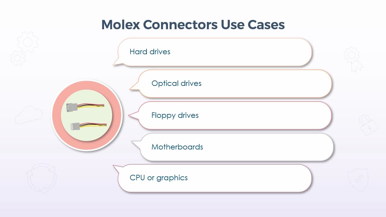
- Identify the different types of Molex connectors
In this video, we'll take a look at Molex connectors, which, with respect to the computing industry, we're used almost entirely for power connections for the internal components of your computer. Now, I say the computing industry because there are other industries using Molex connectors, but, of course, we'll focus on the ones that you will likely find inside of your computer.
Now, with respect to the use cases, they were commonly implemented for hard drives, optical drives, floppy drives, motherboards, and the CPU itself, or perhaps a graphics card. Now, of those floppy drives are just about extinct these days, but most of them would still be found in something like a desktop computer. Now, this particular diagram here is for when you have a 4-pin Molex connector, so it's not always the case. There are sometimes more wires than just this, but even in those cases, it's just a repeated sequence of the same 4 wires.
So for the most part, what you'll find are 4 wires, yellow, black, black and red, with pin one being the yellow wire which carries a 12v power signal. Both 2 and 3, the black wires are for grounding and then pin 4 is the red wire which carries a 5v signal. So, it depended on the device that you were plugging in essentially, with respect to which power signal was used, and in some cases both of them might have been used if the device required more power. Now, in terms of the pins that you would see, there were different sizes, again depending on the device, but the typical pin sizes were 1.57 millimeters or 0.062 inches, 2.13 millimeters or 0.084 inches and 2.36 millimeters or 0.093 inches. Now the distinction between these sizes again really came down to what the device type was, but the primary difference between those sizes was the amount
of current it could carry. The 1.57 millimeter pin was the lowest at 5 amps, while the 2.36 could carry the most at 8.5. Now, with respect to that 4-pin Molex connector that we saw the diagram for, this typically was implemented in a single row and this was the standard peripheral power connector for devices such as hard drives or optical drives. So again, the connector itself was probably only about an inch across, and it had four sockets on the connector side, which would be inserted over the 4 pins on the device end. Now you might also see a 4-pin Molex connector configured in just two rows, so there were still 4 in total, but 2 per row, and this was most commonly used to power the CPU or perhaps a graphics card. The 20-pin connector was most commonly used for motherboards, so this would supply all of the power for all of the integrated components on the motherboard.
The connector itself was significantly longer. It was maybe about two and a half inches and it was typically implemented in two rows of 10, but again it just supplied power for everything that was on the motherboard. Now, in terms of some of the characteristics for all Molex connectors, they are all used for power only. There is no data over any kind of Molex connector. It is almost always used for internal components. In other words, you would almost never see an external connection using a Molex connector and in terms of where they connect on the other end, they essentially extend directly out of the main power supply of the PC. So, the power supply itself is really just a metal box, maybe about 4 inches wide, 5 inches deep and 3 or 4 inches high, but that is what provided power for everything in your PC.
So on the inside, if you were to take the cover off of something like a desktop, you would see all of these wires extending out of the back of the power supply, which could then be connected into the appropriate devices using the Molex connector. Now, the general rule of thumb was that if the connector fit into the device, then it would work, something like a hard drive, for example, had the exact same power connector as a CD-ROM, so it didn't matter which one you use. Now, the power supply itself, of course, would not know what would be present in any given computer, so it wasn't uncommon for there to be one or two extras of any given type, which was fine. You simply left those connectors unplugged, but it gave you the ability to add a device later on, should the need arise.
So again, Molex connectors continue to be the standard for internal power connectors even today. So ultimately, the main concern is that you simply have enough connectors for all of the devices and components in your computer. And on that note, I should finish off by saying that if you did not have enough, there were splitters available. So that you could run two devices off one connection, but that generally wasn't recommended, because you could end up drawing more power than the supply can actually provide you with, but the power supply itself is a replaceable component. So, if you needed more power, you could simply remove the existing power supply and get a newer one that probably had a higher wattage overall and more connectors.
18. Video: Course Summary (it_csap121_06_enus_18)
- summarize the key concepts covered in this course
So, in this course, we've examined how to understand basic cable types and their connectors, features, and purposes. We did this by exploring Ethernet cable types and fiber optic cabling, speed and transmission limitations, and T568A and T568B wiring standards. Video, USB, peripheral, and hard drive cables. Common adapters, USB, and fiber optic connector types. RJ-11 and RJ-45 connectors and punch down blocks. DB-9, lightning ports, F connectors, and Molex connectors. In our next course, we'll move on to explore how to recognize, how to install the appropriate type of RAM and storage devices.